The Basics of a Rideau Lock
When the locks were built in 1826-1831, the ideal lift for each lock was 10 feet (3 m). The design of the gates was such that lifts much higher than 10 feet (3 m) were considered dangerous. So, if a 20 foot (6 m) difference of water had to be overcome, two locks were needed. During the building of the Rideau, the smallest lift in one lock was 2 feet (0.6 m) at Kilmarnock, and the largest lift in one lock was 15 feet 2 inches(4.6 m) at Jones Falls. In both cases, it was exceptional circumstances that led to the creation of a lock with a very small lift, and one with a very large lift.
In this description of a lock, we will use an example of a lock with a lift of 10 feet (3 m).
The depth of the lock chamber is determined by the required amount of lift. A lift of 10 feet (3 m) would require a lock chamber at least 15 feet (4.6 m) deep, more likely 18 or 20 feet (6 m) would be used. The first thing to consider is minimum navigation depth. This was nominally set as 5 feet (1.5 m). However, Colonel By was aware that drought conditions could lower water levels and he designed most of his locks to maintain at least 6 feet (1.8 m) of water above the floor of the lock chamber. This depth was based on measured low water levels to that date (1827).
The other factor was flood height. The top of the lock chamber walls had to be higher than the anticipated height of water during spring flood. Since it would be disastrous to have floodwaters "drown" a lock, often a "guard" was placed on a lock, the portion of the lock walls above the anticipated high water level. For instance, it might be anticipated that floodwater would be 2 feet (0.6 m) above the normal water level. To be safe, Colonel By added a foot or two to that number, in this example he might have placed a 4 foot (1.2 m) guard on the lock.
So, now we have the depth of our lock chamber: six feet (1.8 m) of water, plus 10 feet (3 m) of lift, plus 4 feet (1.2 m) of flood guard, for a height of the walls above the floor of the lock chamber of 20 feet (6 m).
 |
| diagram by: Ken Watson, 2000 |
The next item in the design of the lock was the height of the breastwork. The breastwork is the foundation at the top end (upstream/higher water end) of the lock. In most locks, the breastwork is the difference in height from the floor of the lock, to the bottom of the navigation channel on the upstream side. This meant that less excavation was required on the upstream side, and the upper lock gates only had to be the height of the upper navigation depth plus any guard height that might be required, since it sits on top of the breastwork.
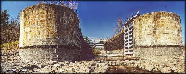 |
Upper Lock at Jones FallsThe chamber is drained revealing the whole lock. The water mark on the wing walls shows the normal 5.5 foot (1.7 m) navigation depth in the chamber. At the upper end of the lock is the breastwork, with the smaller, upper locks gates sitting on top. The upper gates are closed, but the lower gates are open, sitting back in their gate recesses.
photo by: Ken Watson, 2000 |
In our example, the lower lock gates would have to be at least 16 feet (4.8 m) high [6 feet (1.8 m) of water navigation depth plus 10 feet (3 m) of lift]. However, the upper gates only have to be opened or closed when the lock is full to the upper navigation level. This means that the upper gates only have to match the upper end's navigation depth, unless they are also raised to the full guard height. In our case, assuming they are the full guard height, they would only have to be 6 feet (1.8 m) (navigation depth) plus 4 feet (1.2 m) (guard height), or 10 feet (3 m) high. This means that the breastwork in our example would be 10 feet (3 m) high (the amount of the lock lift). A general rule of thumb is that the height of the breastwork is the height of the lift of the lock.
The base of a lock gate rests against a sill, made of either wood or masonry depending on the circumstances. Wood was used if the sill would be constantly underwater (most of the lower gate sills) and masonry was used if the sill would be exposed to air (most of the upper gate sills and a few of the lower gate sills). Today, most of the wooden sills have been redone using concrete.
The height of the solid portion of the gate was usually a foot or so below full guard height, to allow water to run through the lock, rather than over the locks, in the event of an extreme flood.
Another significant issue for a lock is that it has to be watertight. This is not only to keep water in the lock, it is also to keep it out. A lock placed in the middle of navigation channel is in essence a dam. The hydraulic pressure against the entire structure is the difference in water level from the upper side to the lower side of the lock. That is a tremendous amount of pressure. Spring flooding could add another 2 or 3 feet (0.6 - 0.9 m) of pressure on a lock. The wing walls (end walls) on a lock prevent water from eroding the edges of the lock. When a lock was built, clay puddle (clay mixed with sand and gravel, and beaten until it was compacted and made watertight) was put in a two-foot (0.6 m) thick layer against the outer side of the masonry walls of the locks. In addition, timber sheet piling would sometimes be driven ahead of the breastwork to keep water from seeping underneath.
Much of a lock is not visible to a person looking at it today. The walls are eight feet thick (2.4 m) at the base, tapering to five feet (1.5 m) thick at the top. Much of the wall was made of cemented "rubble stone", with the inner side of the lock wall faced with dressed (cut) stone. There are four foot by four foot (1.2 m) masonry piers reinforcing the outside of the lock walls every 20 feet (6 m) or so (sort of like buttresses).
If the lock was excavated in solid bedrock which was deemed to be watertight (no leaking fissures), then this bedrock was left as the floor of the lock. However, a lock excavated in clay or fissured bedrock required an artificial bottom. This would have normally been an inverted masonry arch, a shallow arch made of cemented stone. In eight of the locks, in order to save time and money, wooden floors were substituted. Colonel By noted that wood, when kept underwater, is as durable as stone. He was correct, wooden floors, kept underwater, lasted many decades before needing repair or replacement. When the wooden floor of Lower Brewers was rebuilt with concrete in 1977, test on the sleepers (large timber foundations), showed that the wood was still sound after being underwater for 145 years.
One of the main features in the design of a lock is how to let the water in and out. At the upper end of a lock, wall sluices (tunnel sluices) were used. These were tunnels that led from the upper part of the lock, ahead of the gate, through the lock wall to enter the lock at the floor of the chamber below the gate. Hand winches (crabs) or rack and pinion mechanisms were used to open and close valves at the entrance to these wall sluices.
To let the water out of a lock, valves were placed directly in the lower lock gates. These are opened and closed by simple rack and pinion mechanisms. The reason these gate valves are not used in the upper gates is the fact that most of the upper gates are sitting above water when the lock is at its lower navigation level. If the valves were in these gates, the water would spray into the lock like a fire hose. With tunnel sluices, the water enters underwater, mitigating turbulence. In the very few locks that were built without breastworks (Newboro, Narrows, Kilmarnock, Clowes, and Beveridges), there are no tunnel sluices and the valves were built into the upper gates, since the base of these gates are always underwater.
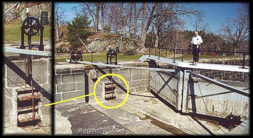 |
Top Lock of the Lower Flight at Jones FallsThe top lock of the lower flight of 3 locks at Jones Falls, showing the small gate on top of the breastwork, and the valves in front of the tunnel sluice leading into the lock. The photo on the left is a close-up of the sluice valve and rack and pinion mechanism.
This lock doesn't have a guard on it, the water level goes almost to the top of the chamber walls. This is because the Upper Lock at Jones Falls acts as a guard for this lock. Most "middle locks" don't have a guard.
photo by: Ken Watson, 2000 |
Another feature of a lock is that recesses are built into the walls so that the gates lie flush with the walls when opened. This is done so that vessels don't damage them and allows the full width of the lock to be used.
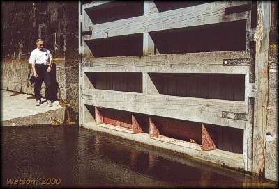 |
Lower Gate ValvesLower gate of upper lock at Jones Falls, showing the two gate valves near the bottom of the gate. These are opened and closed using rack and pinion mechanisms sitting on top of the gate.
photo by: Ken Watson, 2000 |
Both above the upper gates and below the lower gates, slots were put in the masonry to allow squared timber to be dropped in, damming the top or bottom of the lock. These slots, called Stop Log Checks, are used to this day. In the winter, stop logs are dropped into the upper slots, allowing the lock to be drained to the lower navigation level. This takes the pressure off the upper gates for the winter and also protects the gate and sluice valves from ice damage. If a lower gate has to be repaired, stop logs are dropped in the lower set of slots, allowing the chamber of the lock to be pumped dry, and the gates repaired or replaced.
 |
Stop Logs in place at Davis LockThe stops logs are sitting in their checks (slots) on the upstream side of Davis Lock, holding back the water of Opinicon Lake. This will take the pressure off the upper gates through the winter. The upper gates are kept closed in the event of a failure of the stop logs. The sluice tunnel valves in this lock are opened and closed using crabs and chains.
Note in this picture the water mark of the normal water level. The gate has about a two-foot (0.6 m) guard against high water, the walls of the lock a three-foot (0.9 m) guard.
photo by: Ken Watson, 2000 |
In multiple sets of locks, or locks above a basin such as at Jones Falls, the locks are usually drained dry in the winter.
The gates of all the locks are built of wood, with the exception of a couple of locks with steel gates that are opened and closed by electrically operated hydraulic cylinders. For the first fifty years or so, the lock gates were made of native oak. These gates were extremely durable, lasting about 20 years. Each gate had to be custom fitted and they were built on-site. The master carpenter would be in charge of the final hanging of the gate, making sure it had a proper fit. The gates, when closed, meet at an angle such that water pressure forces them tightly closed.
By the late 1800s, Michigan oak had to be substituted for native oak, and the gates became less durable, only lasting about 15 years. Today the lock gates are made of Douglas fir obtained from the west coast of North America (usually B.C.). They last about 15 years and are made at the shops in Smiths Falls.
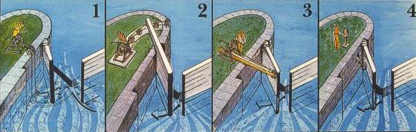 |
Rideau Lock Gate Opening Mechanisms
diagram by: Parks Canada |
A variety of gate opening mechanisms have been used over the years. The first mechanism was the "endless chain crab system" (#1 in diagram), which consisted of chains wrapped around the drum of a hand winch (crab). The chains ran down the wall of the lock and across the floor through a series of pulleys. The chains were attached to the base of the gate underwater. This configuration resulted in gates jamming on occasion, as debris would clog the chains and pulleys. Examples of this type of mechanism can still be seen today at Kingston Mills and the Ottawa Locks.
In 1835, a new mechanism (#2 in diagram), the "swing bar/crab system" was installed. Chains were led through pulleys to an extension of the upper part of the lock gate called the swing bar. This kept the chains above the lock wall and they were not subject to jamming. This type of mechanism can still be seen at many of the locks today, including Ottawa, Hogs Back, Old Slys, Edmunds, Upper Nicholsons and Kingston Mills.
In 1895, another new mechanism (#3 in diagram), the "push bar/crab system" was introduced. This system used a single bar attached to the upper corner of a gate. Chains attached to the bar pull the gate open or closed by using a hand winch (crab). Most of the locks currently use this system.
In the 1960s, a few of the locks were converted to an electric/hydraulic system (Newboro, Black Rapids and Smiths Falls Combined). A hydraulic cylinder is used to pull the gates open or push them closed (#4 in diagram).
Of course the best thing to do in order to appreciate and understand the elements of a lock is to visit one and see it in operation. Talk to the lockstation staff and have them explain exactly how each element of the locks works.
|